![](https://blogger.googleusercontent.com/img/b/R29vZ2xl/AVvXsEjoiokESHoFRGkD6caK_9pQ1vyHd46gblulCWHENCqIMiz2QstBZLEX0xe1bJxLX_Qhrf43ReTQhfUFSAoTB1pn-yB9yVIvcD_ATYMusS8KP1gFZFtKa42lo9BvOgpawm-5gs0JbNsyTgXb/s320/2015-09-19+15.17.09.jpg) |
SVTrackR SMD TNC |
In my learning process of making my own DIY PCB and after ordering some common SMD components ( capacitors, LEDs &, resistors ), I decided to design a small and functional TNC that only need 4 connections to handy and a few jumper wires to Arduino.
*** This is the first time I ever successfully made a DIY PCB.
Let's start with the design on EagleCAD ..
![](https://blogger.googleusercontent.com/img/b/R29vZ2xl/AVvXsEg6T9EYvB1KtQZ6VOkaorQSUeHgmE-stftQV0b-sGASsBk_qIqBpS8-P8fhSC7tMnYfkEm5a1db5H0V2rsxbkdAXdBi_PTIjvVEp6_6qLqSmcuIpuzyNCc5YOrLH7ANMibJpj56pBoegDLN/s320/SVT_SMD.png) |
EagleCAD SVTrackR SMD |
I designed this small 28x23mm board for fun and to learn on how to solder SMD parts on DIY PCB. I made everything on a single layer. The only drawback is the two red and green LEDs are at the bottom where the copper traces are located.
Generate gerber and do a 3D view of the board. This method is easier to spot any errors.
![](https://blogger.googleusercontent.com/img/b/R29vZ2xl/AVvXsEgyfOBBKXv0cELz_MginINlllzEFaZYrdFTlCiDsNy1RCjQmnDRjUvtYtEOcBWiIQ1CBgEZm-zZ40isaZ8DxzfUJQpWNcrnuntnUvdagkbJ6dEUPX2CtiV_uOV0co41Yf02wUUqONKwMarK/s320/SMD+Modem+V3+3D.png) |
3D Gerber view |
![](https://blogger.googleusercontent.com/img/b/R29vZ2xl/AVvXsEjYi9N5AJhrF-FL_TzAFiVUySPlOC5M_FMKerNZq2mCzFILuFaocIkOzZzwvc0fSCyyRkd0EOtmiKCX04kV38SoHfb0NAhJcv3ASosjfpOgjYnSw7ovB33o53r8xB0mI5jBE4QPwT1ekMXo/s320/EagleCAD+tracing+paper.jpg) |
Printed out for UV transfer to UV PCB |
This is the tracing paper before the UV treatment. Thanks to Uncle Chow, 9M2CF made me a nice photo frame to hold the UV sensitive PCB and tracing circuit in place.
![](https://blogger.googleusercontent.com/img/b/R29vZ2xl/AVvXsEitOR03HCLuCuISXxHMCuLlXeECCW3atyzYrZbzVxjsXspy3T0rPCGDi6jQ8F2_wEYfdOXFmYEkcD8TmFCwiAoltBGihUdwFxMk7pssXj9-w1lvY6h6Y6NBF_YkTYclVzBy2pSutyarTMya/s320/2015-09-19+01.50.09.jpg) |
PCB holder / cover |
![](https://blogger.googleusercontent.com/img/b/R29vZ2xl/AVvXsEgYEt9ukSoAgN__jy6X4OBR2ogTa9nR_BlRthqBJ1kCYvXTNamNP8J5gFPpTXCFC9ULksJYACUibT-mprAC1HSfNUaLfzq2wyYF0RKLw5udH8kS9TSF-gommLZy92Smje0kdfFwfHIET8-w/s320/2015-09-19+01.50.39.jpg) |
UV lightbox |
![](https://blogger.googleusercontent.com/img/b/R29vZ2xl/AVvXsEgGjpmkbxfnrq2l4Qa846vmbjvIoDKT5oSBUPuVkToDbNfrfoIDvyGX6nK5MsaGwl7n1bjY1FF94N79UTIo72r-2Gwzms8EReNo9DfunG1NazAhkZFzQFsHubc-9ZcV58uPZcLWStScaL22/s320/2015-09-19+01.50.49.jpg) |
UV lightbox UV LED turned on |
![](https://blogger.googleusercontent.com/img/b/R29vZ2xl/AVvXsEhStEf7cNyLZKjsUxuN8aXGXbCV-XlIfYOZd37NfMYJ283yhnp9qh3xIJlDzxSiiltQYUo8fC3IjvJ7bYbBY2nw4RwoSKWmQNYILOHhyphenhyphenWp9geiM1bXcL1vgXzTW8jCRyEtuGRSgvvB-59dE/s320/2015-09-19+01.51.55.jpg) |
UV lightbox and photoframe cover |
After like 15mins ( long duration was due to the diffused and evenly distributed UV light ), I drop the PCB into sodium hydroxide 0.7%. This is removed whatever parts exposed to the UV light and leaving the green part for second steps.
![](https://blogger.googleusercontent.com/img/b/R29vZ2xl/AVvXsEg3IaU5_tMBxhhCV4dleYEm7Cf0orE70Et6RffomxAjPbV38QxdzZKgHLjK9bMku4bGjpdX980vy_X4bRchiRBd6hvRCsjdQlq2WX1pp2NL4VBz6mZlGQgxNXGw1B8iDBYp3-2qQa-Gwy0E/s320/2015-09-19+01.30.54.jpg) |
Exposed copper after Sodium Hydroxide bath |
Once the Sodium Hydroxide bath was done, I wash it and dump into the second solution - Ferric Chloride to eat away all those exposed copper.
![](https://blogger.googleusercontent.com/img/b/R29vZ2xl/AVvXsEgdm9pZqZUFgm12kSr9P1sBS2_lbL7E8xcumtXgmxePaeOPCMGJXh-1VJd4yfwwyaOQRVjsckxMKx656fut6Z47EqcrAx-pc4d24SHoe8p0tQXlzWeZ3ceBKXByLSeIBfx7vXFH7qBA4eRg/s320/2015-09-19+01.42.35.jpg) |
Ferric Chloride bath |
After a few shakes and turns, all the copper were wash away leaving the green portion of the copper traces.
I use thinner to clean away the green stuff and leave you with a shiny copper traces. Not bad for a first timer doing SMD PCB.
Now for the drilling and soldering part. A tip from 9M2CF, always solder before drilling as the solder will guide the drill bit into the holes to be drilled.
![](https://blogger.googleusercontent.com/img/b/R29vZ2xl/AVvXsEgL94TQZFadzLj2QSt9_bmnUm-gJPsZ3DUUb8tdfqwNmztS-zj8TaZmv0n4mLdM-EiuVt1F6jqGB9EBH706ER_Qke2X9GcbwWe2Donn_H3Xzm9gFYCnulwg8WooPOmAUeZkl_QH1gCViN2K/s400/2015-09-19+10.54.12.jpg) |
Drilling holes |
![](https://blogger.googleusercontent.com/img/b/R29vZ2xl/AVvXsEiFJo75DaJKrJcfMvw3eKXsXW-6A8OJlDO0Gy04q_CKKp8pAiNp-IC2RPhv1sa0QY-jE3B1BMm1gn866dAH2Foywa2ZpOg7tGdIrqHu22WNkgmhbALQOVy2dF_Yb8ipq6nTHV2qBEgeAvH4/s400/2015-09-19+11.00.45.jpg) |
Soldering SMD resistors |
With too much solder at the pads, those SMD 1206 resistors are uneven on top ... or I was using a really fat tip.
![](https://blogger.googleusercontent.com/img/b/R29vZ2xl/AVvXsEhpzSvv7XqHYSD8Cbmtl9nFOE4LyvVPwR0IMFIN1udNTwy-z8ISwGgpyatvr_Lypy94yFtVImNHC1PlcddFAjKwAgdc6BmcD6o9M-z3LlW2gtspNBz7SeK0NM3ym3tVFweGrhuOWSE2lI7D/s400/2015-09-19+11.42.52.jpg) |
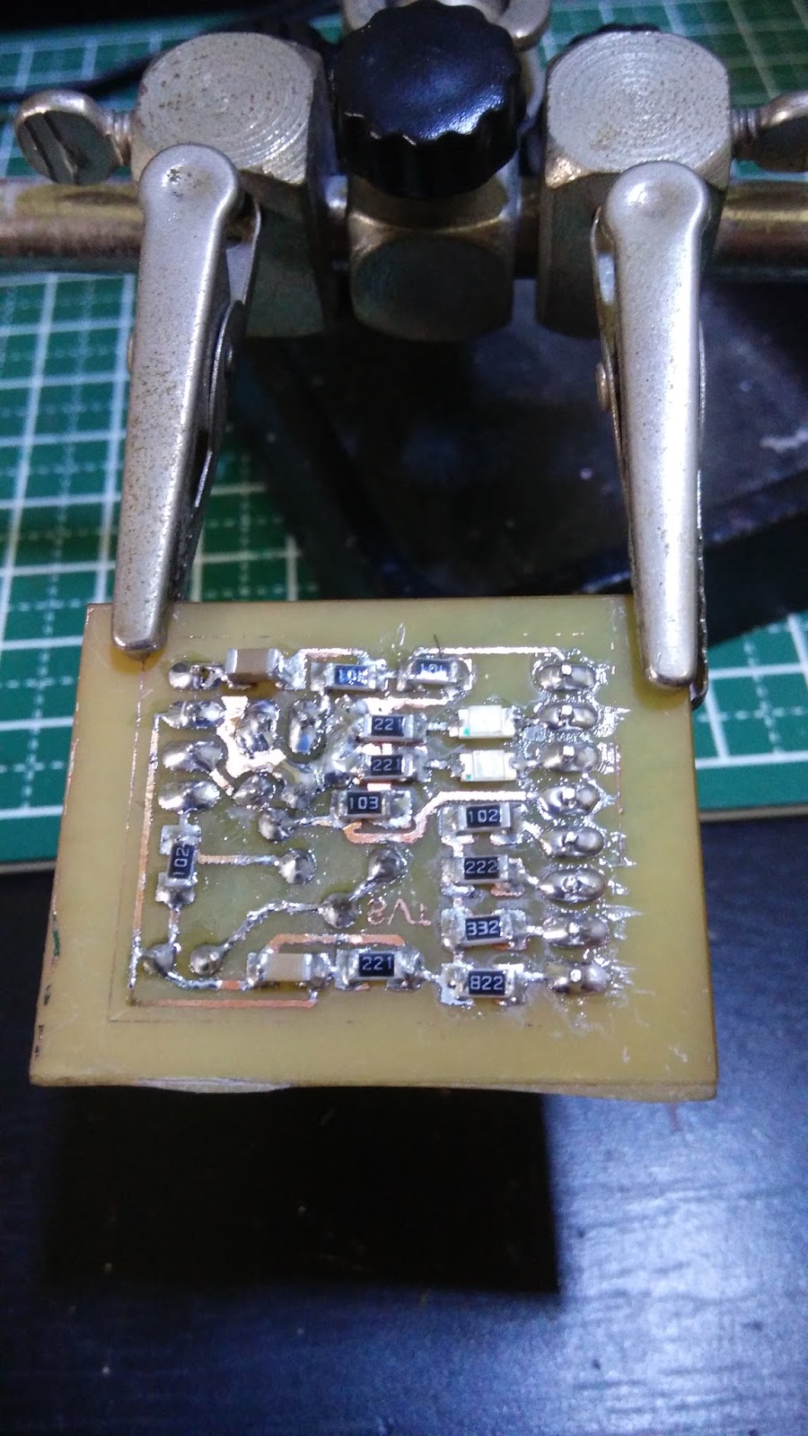
SMD SVTrackR TNC back |
![](https://blogger.googleusercontent.com/img/b/R29vZ2xl/AVvXsEiAhiR_PeiXhhjesHhNng35v4SDVLHH3JiCmcrjvYcPebIB-EIQvno-S6CAiebJ8BrLuQ5Ll9r9ndRsaiHzh76mx3PKjrOZoHGtGucByLYvywgDB7WJVErwOgf6HdyFERlZGCm7BRZxuGno/s400/2015-09-19+11.41.02.jpg) |
SMD SVTrackR TNC front |
After a while, got all the SMD and through-hole parts soldered. Need to find the SMD parts for the 100K POT. This is the one I currently have in my part inventory.
![](https://blogger.googleusercontent.com/img/b/R29vZ2xl/AVvXsEh7-nRZh8efdDjpX4EZTKgEo_UmsmQdAdV9TFn_W9wZMHSxxxOkNmliEdQjdyRZ1I61-B5tQubx8Dp-GqE-YkvwRVGoIslL1NT_qHFIFMZ7duwth7x-4fUpTWfP8x4UwKP_gur_6BiJ68vx/s400/2015-09-19+14.53.38.jpg) |
Add caption |
Comparing sizes between the old MicroModem with Mini Pro and the new SMD TNC that will run from either Arduino Mini Pro or Arduino Nano.
Thanks for sharing such a descriptive blog. I learned so much from this blog.
ReplyDeleteM83513 connectors
Hi Stanely, My name is Dave (VE4NEG). I'm very interested in APRS. I would like to learn how to build a TNC from salvaged parts.
ReplyDeleteOur ham radio club purchased a NET51TNC but didn't get the needed software. Would you happen to have a copy of the NET51TNC software?
All the best
73 Dave
This comment has been removed by a blog administrator.
ReplyDelete