Saturday, September 19, 2015

Making of Surface Mounted (SMD) DIY PCB TNC


SVTrackR SMD TNC

In my learning process of making my own DIY PCB and after ordering some common SMD components ( capacitors, LEDs &, resistors ), I decided to design a small and functional TNC that only need 4 connections to handy and a few jumper wires to Arduino.

*** This is the first time I ever successfully made a DIY PCB.

Let's start with the design on EagleCAD ..

EagleCAD SVTrackR SMD
I designed this small 28x23mm board for fun and to learn on how to solder SMD parts on DIY PCB. I made everything on a single layer. The only drawback is the two red and green LEDs are at the bottom where the copper traces are located.

Generate gerber and do a 3D view of the board. This method is easier to spot any errors.

3D Gerber view


Printed out for UV transfer to UV PCB
This is the tracing paper before the UV treatment. Thanks to Uncle Chow, 9M2CF made me a nice photo frame to hold the UV sensitive PCB and tracing circuit in place.

PCB holder / cover

UV lightbox

UV lightbox UV LED turned on

UV lightbox and photoframe cover
After like 15mins ( long duration was due to the diffused and evenly distributed UV light ), I drop the PCB into sodium hydroxide 0.7%. This is removed whatever parts exposed to the UV light and leaving the green part for second steps.

Exposed copper after Sodium Hydroxide bath
 Once the Sodium Hydroxide bath was done, I wash it and dump into the second solution - Ferric Chloride to eat away all those exposed copper.

Ferric Chloride bath
After a few shakes and turns, all the copper were wash away leaving the green portion of the copper traces.


I use thinner to clean away the green stuff and leave you with a shiny copper traces. Not bad for a first timer doing SMD PCB.

Now for the drilling and soldering part. A tip from 9M2CF, always solder before drilling as the solder will guide the drill bit into the holes to be drilled.

Drilling holes
Soldering SMD resistors
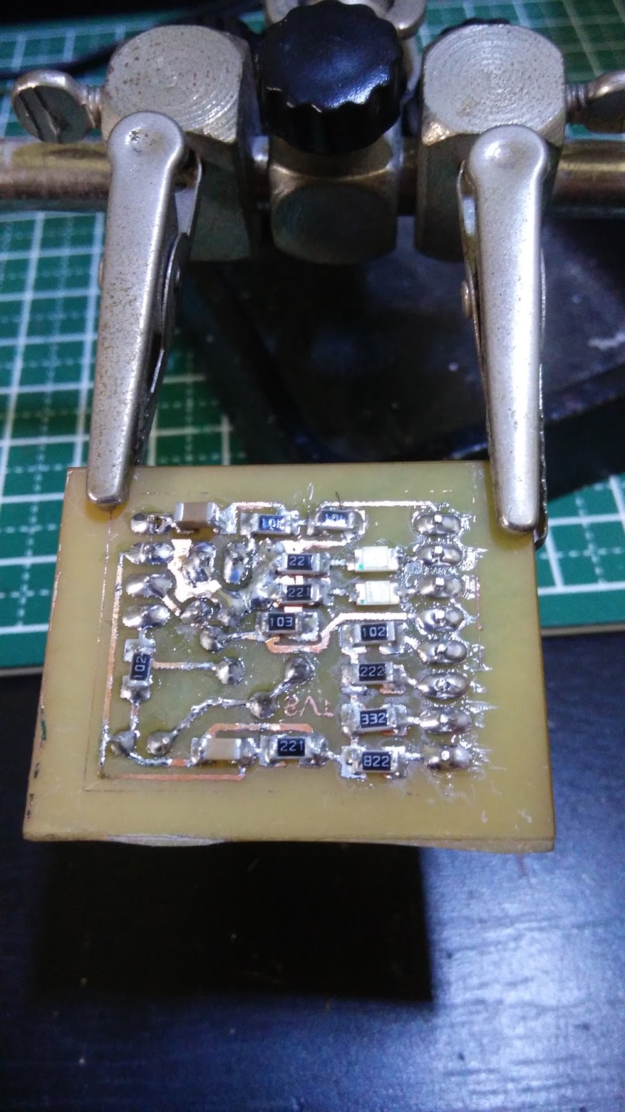
With too much solder at the pads, those SMD 1206 resistors are uneven on top ... or I was using a really fat tip.

SMD SVTrackR TNC back

SMD SVTrackR TNC front
After a while, got all the SMD and through-hole parts soldered. Need to find the SMD parts for the 100K POT. This is the one I currently have in my part inventory.

Add caption


Comparing sizes between the old MicroModem with Mini Pro and the new SMD TNC that will run from either Arduino Mini Pro or Arduino Nano.


Saturday, September 5, 2015

SVTrackR 1.62 : Dashboard speedometer & APRS Decoder

SVTrackR I2C LCD


One of my users suggested that I split the display from the APRS Tracker so that he can placed the SVTrackR together with the handy below the seat. I liked this idea and explore the unused I2C pins on the Arduino Mini Pro.

Once I found out that the I2C can goes up to 6m of length, I made a 1 meter cables and started my tests on the Eduboard I built with Serial and I2C header pins at the bottom right of the blue PCB.
I have also connected a APRS Modem to the Serial Rx,Tx pins.


SVTrackR 162 on Eduboard


Once I finalised to use the blue 16x2 I2C LCD, I search on Thingiverse for a 3D printed casing. I found this one below suitable and ask around for pricing and where to get it printed.

16x2 LCD I2C 3D casing
As I made my codes with #ifdef definations for OLED, I just added more #ifdef for 16x2LCD and format the display according to the size of the LCD, 16 characters by 2 rows. As these screen are physically bigger than the 0.96 OLED, the resolution is only 16x2 text whereas the 0.96" OLED can goesd up to 7 lines of 25+ characters.

As my main screen should be the large digital speedometer with number of satellites being tracked and heading in degrees, I will rotate to 2 other screen for other statistics like Rx, Tx packets, distance to base and altitude from the GPS receiver.

In order to displayed decoded packets, I wrote a checking to display the decoded packets for 10 seconds before switching back to the speedometer.

Below are some of the images taken from my dashboard, it fits nicely with the large number displaying the speed or other info.

SVTrackR on dashboard

SVTrackR decoded packets

16x2 I2C LCD during initial tests


I am still in the process of getting a 3D printed casing for this.


Tuesday, August 4, 2015

Tuning HF antenna with SWR Bridge and Rigol Oscilloscope

After viewing this Youtube video from W2AEW on #112: Use an Oscilloscope and Signal Generator help tune an HF Antenna, measure complex impedance, I decided to do a similar SWR bridge with a AD9850 as a signal generator.

Front of SWR bridge

Back of SWR bridge

SWR bridge with 3W 50ohm and 2x1K resistors
The actual circuit was on the above mention Youtube video.

SWR bridge mounted on Dremel Vise


Arduino + AD9850 + 8digit 7segment with VFO
I had the AD9850 on top of the Protoshield with a large 8 digit 7-segment display as the signal generator frequency with a rotary encoder as a VFO.

Sinewave of 50ohm compared to 50ohm terminator
Almost match impedance
The connection from the SWR bridge are BNC connector with a T-joint to the Rigol DS1052E with a 50ohm terminator. This ensure both ends are 50ohm terminated.

 To check the HF antenna impedance visually, turn VFO to the desired frequency and visually check the yellow (50ohm reference) and blue ( antenna ) sinewave. The above image is an almost match impedance. Once the two sinewave are close enough, turn the coax switcher to the IC-7200 and the SWR reading will be quite low.

Unmatch impedance
The above is an example of an unmatch impedance, with such big differences in the sinewave, it is almost certain the SWR reading on the IC-7200 will be very high.


Icom IC-7200

Finally got my first HF rig, a Icom IC-7200 (in Feb 2015) ..


MX200 Tuner, IC-7200
The Icom IC-7200 comes built-in with USB soundcard and IF DSP, the two features that are mostly found in higher end HF rigs..

Icom IC-7200

IC-7200 with MX200 Tuner

Power Supply, IC-7200 and MX200 tuner


KL Foxhunt and Emcomm APRS booth


Emcomm GoBox 2015
Here are some pictures of items displayed in APRS booth during KL foxhunt and Emcomm event in Kuala Lumpur.


RPi + aprx , SVTrackR + Maps, SVTrackR + OLED


Various APRS gadgets

Team Ham United


Ham United GoBox


Friday, December 12, 2014

APRS Arduino with map display

APRS Map on 2.2" TFT


While reading the chapter on Marinus: An APRS Display from the Ham Radio for Arduino & Picaxe by Leigh L. Klotz, Jr, WA5ZNU. I decide to give it a try over the weekend.


Ham Radio for Arduino & PICAXE

Initially it sounded complicated but after looking into my inventory ( Arduino, TFT display, SD card and APRS modem ), I have ALL the similar items needed to do this project.

I replaced the Arduino UNO with a DigiX , an enhanced Arduino DUE with Wifi, SD card, nRF and many more pins. The reason for this was for both mcu power, flash & memory storage and operating voltage of 3.3V as most of the TFT out there runs on 3.3V.

The next, I replaced the Adafruit display shield with a bigger and commonly used  2.2" TFT / ILI9341 (320x240) that runs on SPI. The Arduino forum here have lots of info on this display. This display runs on 3.3V only. As I have gotten this 2.2" TFT working on Adafruit GFX library before, it is just a matter of hooking up the pins correctly.

The SD card slot was built-in to the DigiX on pin 87 as Chip Select (CS). Nice...


MicroAPRS modem


The last piece, instead of Argent Radio Shield, I'm using an Open Source version of Arduino MicroAPRS modem by markqvist from unsigned.io. The above is a picture of the MicroAPRS modem board I made on DIY PCB.

For the library, DB1NTO modified the ArgentRadioShield library for the MicroAPRS for decoding the normal and compressed packets functions.

All the main codes remains the same as I just modified the TFT & ArgentRadioShield library only.

The image below are the whole system, DigiX with SD card, 2.2" TFT display, 5V to 3.3V from the MicroAPRS modem to the Serial3 of DigiX.

Marinus on DigiX / MicroAPRS
With help from the author WA5ZNU, I was able to generate the OSM map tile for 320x240 to match my 2.2" TFT display. Since I'm using a "bigger" Arduino with lots of memory, I generated a 7x7 tile to be stored inside the SD card.

OSM 7x7 map tiles

With everything setup, I put everything inside a plastic box and go for a ride. Below are some of the pictures and decoded callsigns on the maps.

APRS Map decoding my 9W2SVT-8 packets


APRS Map inside a plastic box


9W2SVT-8


9W2RUT-2

Summary hardware :-

Special thanks Leigh L. Klotz, Jr, WA5ZNU for the great article and his assistance to get everything up and running. Markqvist for the MicroAPRS modem and Taner DB1NTO for the modified MicroAPRS library to support for packet decoding for normal and compressed packets.


Summary Links :-


Wednesday, December 10, 2014

Updated SVTrackR with mini 0.96 OLED display

After a few months of testing and development, I have reach a milestone of version 1.0 with all the necessary functions and features.

SVTrackR with OLED
The functions and features of this APRS Tracker called SVTrackR are :-

  • Super bright 0.96" mini OLED display
  • Decodes mic-e / compressed packets
  • Calculate distance to station from received packets
  • Calculate bearing to station from received packets
  • Display two decoded packets in multiple lines
  • Decodes and display messages for the callsign
  • Top section display GPS lat/lon and number of satellites
  •  Lower section display important counters, speeds, heading and altitude
  • Enhance Smart Beacons 
  • Calculate distance to base station location
  • Display uptime / minutes since power-up
  • Sequence number of every packet to detect packet loss
  • Byte saving by sending status every 10 packets
SVTrackR message

The OLED screen are bright enough during the day and are made for you to glance it during stops. It was NOT design to view it during driving as the text are too small.


The mic-e / compressed packet was decoded as 9M2NIA-9 was 142 degree, 6km away from my current location.
SVTrackR mic-e decoded